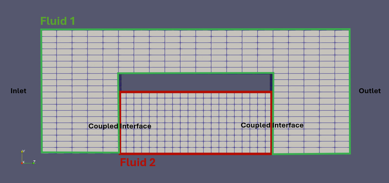
I have a relatively straight forward surface coupling case, which I am having trouble with and I hope someone can help: I am performing fluid-fluid coupling with a custom solver. Below is a simplified case setup, that illustrates my issue. I have one Fluid-1 domain and another Fluid-2 domain, which is surface coupled to the mesh of Fluid-1. My coupling variables are the volume fraction (alpha) of a liquid along with its gradient, the pressure+gradient and velocity+gradient at the interfaces. A pressure difference is set between the inlet and the outlet, I would like the liquid to simply flow through the structure shown below. I use the same boundary conditions, as I do for cases without the coupling, the only difference is that at the coupled interfaces I use a coupledVelocity and coupledPressure boundary condition.
Its not as continuous as I would have expected and even looks somewhat inverted (like at the coupled interface on the bottom right). Do you know if this is a problem with my precice configuration? And if so, what would I have to do to change this? I have attached my precice-config.xml below.
Could you maybe give more details about the solvers? Are they both compressible solvers?
Coupling both values and gradients for both velocity and pressure is not necessarily the best setup. In our tutorials, we typically do not couple the pressure gradient:
(see also the linked study and Markus’ thesis for more examples)
Not sure if this is the reason, though. How does the flow look like until that point? Does it start fine and eventually introduce errors, or is it completely wrong since the beginning?
How do the 0/U, 0/p, and 0/alpha files look for both solvers?
yes, they are both compressible, porous media solvers. I have added the boundary value files below for Fluid 1. The shared boundaries are the coupledInterface in Fluid-1, that is coupled to the inlet and outlet of Fluid-2.
It might be important to add, that this only happens when i couple my solver on two interfaces. If I have only one patch (similarly to the partitioned-pipe-two-phase tutorial), then everything works as expected
This is the fortunate case: we have something clear and easy to check!
I see a few issues in these files:
Fluid 1: Why is there only one couplingInterface? These interfaces are separated. I would define two, one for each coupled surface.
Fluid 2: Why are both alpha boundaries fixedValue? Aren’t you reading a gradient in one of the interfaces?
Fluid 2: Pressure:
Why are the walls defined as fixedFluxPressure? Should be zeroGradient.
In the examples we have, we typically define coupledPressure in the one side, and fixedValue in the other. But I think coupledPressure in both should work, as it changes type per direction of the flow. Same for velocity.
Thanks, Makis! I tried out your advice and changing to two coupling interfaces and using coupledPressure along with fixedValue solved some of the issues. Now the pressure function is looking the way I would expect it. I still have a problem with my alphas though - the Fluid-2 domain does not get filled (at the point I would expect it to start getting filled, the pressure - understandably - does strange things). You mentioned that the gradient should be read on one of the interfaces. Currently, Fluid-1 reads the alpha gradient and Fluid-2 writes the alpha values. I thought I could either read or write with one mesh, how would I split this up in my configuration?
Yes, of course. They are attached below, the couplingInterface1 in the Fluid-1 patch is connected to the inlet in Fluid-2 and couplingInterface2 in the Fluid-1 patch is connected to the outlet in Fluid-2
What do you mean to “make the mesh readable and writeable”? In terms of meshes, this works already. I think it is still confusing that preCICE has both coupling interfaces (OpenFOAM patches) in the same mesh. The config file currently has:
Fluid1-Mesh
Fluid2-Mesh
You could make it:
Fluid1-Upstream-Mesh
Fluid1-Downstream-Mesh
Fluid2-Inlet-Mesh
Fluid2-Outlet-Mesh
The preciceDict for Fluid1 would then be something like (not tested):
Where the gradient of a field is read, the boundary condition needs to be fixedGradient. Where the value is read, the BC needs to be fixedValue.
It is a bit arbitrary on which participant to read values and on which gradients of each field, but typically we don’t read only values or only gradients on one patch.
You would need to modify your precice-config.xml as well to define the additional meshes, and add two more mappings. This is more complicated than two pipes in series, but again the case itself is also more complex.
Sorry to open this up again, it seems that the issue I had with the alpha values is not resolved after all: in the beginning, the simulation looks fine, however once the alpha fraction begins to fill the domain of Fluid-2, a large pressure gradient between Fluid-1 and Fluid-2 builds up, however the fluid does not enter the Fluid-2 domain. Besides that the alpha values get values >1 in this area. I assume there is something wrong with the left coupled interface, I am unsure what it is though. Below is a screenshot of the pressure distribution right after the fluid begins to enter the FLuid-2 domain. Do you know what could be causing this?
However, I do have different variables in my solver, such as temperature and some material properties (defined as a variable, they are only used to set up the porous media domain), which I create, they are not part of any calculation though (I commented out TEqn.H for simplicity) and are therefore not coupled. Do you think this might cause problems? The variables themselves are hardcoded into the derived solver I am using and simply commenting them out isn’t so easy, therefore I haven’t tested removing them. If you think they will cause issues, I will try though.
Furthermore, I have the pressure p derived from the reduced pressure p_rgh, which I am not coupling either.
No, if they are not contributing in the computations, there is no reason to couple them.
This might be an issue. Why are you defining nameP p_rgh;, if you are not using it?
I find it interesting that the problem appears when the phase changes, thinking that there might be phase-related variables that the adapter does not couple (some solver split, e.g., U into U.air and U.water).