Hello everyone!
Continuing the discussion from Data mapping in preCICE: article published:
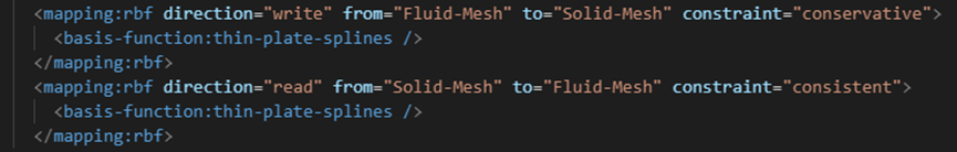
I am working on a FSI problem, where OpenFOAM is used on the fluid side and CalculiX on the structural side. Initially, I had 284,707 nodes on the OpenFOAM side and 3,590 surface nodes on the CalculiX side. RBF mapping was working correctly without any issues.
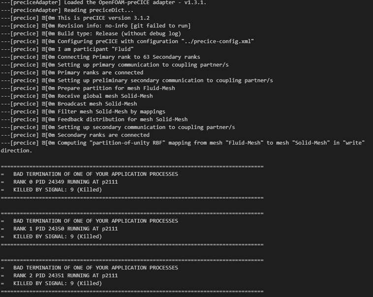
However, when I increased the number of nodes on the structural side to 30,432, I encountered a memory issue during mapping, causing the program to terminate.
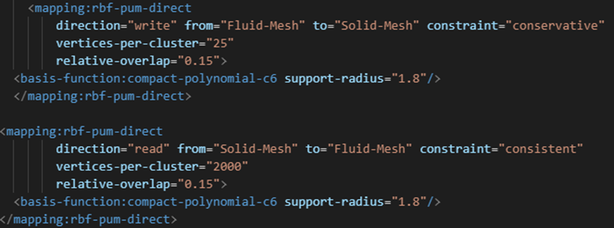
To solve this, I modified the mapping method (as shown in the figure), and the mapping worked fine again.
But when I increased the number of structural nodes to 39,775, no matter how I adjusted the settings, I still couldn’t resolve the issue.I have reviewed the relevant papers, but I have not yet found clear debugging strategies that address my issue. I am curious as to why the RBF method might struggle with large-scale node mappings, particularly since the first-order nearest-neighbor mapping works without any issues.
Has anyone encountered similar issues have any suggestions on how to address this. @DavidSCN could you please provide any insights or suggestions on this issue? I’d greatly appreciate your expertise in understanding whether this is related to memory limitations or other aspects of RBF mapping. Any help or suggestions would be greatly appreciated!
Thanks a lot!
If I understand your problem correctly, RBF interpolation can be extremely costly, as it relies on heavy matrix computations behind the scenes. Furthermore, if you’re not using a method like Partition of Unity (PUM) or locally-supported RBF, the kernel matrix generated using your chosen RBF may be ill-conditioned, which can cause the solver to fail, although I believe preCICE will notify you in such cases.
The PUM method helps alleviate some of these issues by dividing the domain into smaller clusters, making the problem more manageable. An article written by David Schneider and Benjamin Uekermann, published in 2025 (there’s a post about it on this forum), explains this in detail.
You should also consider fine-tuning the support radius and vertices-per-cluster parameters to improve your results. 2000 for the vertices_per_cluster parameter seems a bit high, given that the default is 10. Reducing either of them might help with performance or stability. But I’m by no means an expert.
What can possibly go wrong?
The mapping could fail either because
- the choice of the support-radius produces ill-conditioned matrices
- the clustering fails to generate a full coverage of your coupling meshes
preCICE tells you at runtime if you hit either of those scenarios. Since you run your code MPI parallel, the MPI termination shadows the preCICE error message. Depending on your logging configuration, you should still be able to identify which of the two scenarios applies to your case. So identifying this would be step one.
In case you hit error message one:
- you could either reduce the support radius, or use a (less efficient) thin-plate-spline function for robustness reasons, which does not exhibit any (tunable) support-radius
In case you hit error message 2:
- before changing any configuration option, it’s worth to check that your coupling meshes are actually describing the same geometry. The error message would also tell you which coordinate it failed to fit into the data mapping. Hence, check if this coordinate is actually within in the interface or maybe there is a misconfiguration of the interface mesh. You may want to check the preCICE export
<export:vtu ../> for this purpose
- if your meshes fit and you are certain the mapping doesnt capture what it should capture, the first option I would try would be to use
project-to-input=false and run again. Leave all other options at the default
- if that’s not enough you could increase the number of vertices-per-cluster (maybe select 70 or 100 instead of the default (which is 50).
- if that’s still not enough, you can go higher in terms of the vertices-per-cluster, but generally, your interface won’t match well to cope with your scenario. It could for example be that: although both meshes describe the same geometry, your input mesh has a “hole”, i.e., a region simply not represented in the interface mesh, where the output mesh is represented. If the hole is too large, the mapping will fail by to come up with a coverage of the geometry.
Note that the vertices-per-cluster configuration option affects the memory footprint of the algorithm quadratic in complexity. I would consider setting it to 2000 as too large anyhow. Since the difference in resolution seems to be about a factor of 10, the output matrix in each cluster could easily have a size of 2k \times 20k entries, which yields
2000*20000*64/8 \simeq 320 MB per cluster. If you have 100 clusters, then of course you end up with 32 GB only for the output matrices. Depending on the memory consumption of your remaining program and your hardware, this could lead to issues (although I would assume there is some headroom left on a compute cluster).
However, it’s mostly a matter of configuration: Using the default configuration would give you a memory consumption of 200kB per cluster.
P.S. in Sec. 4.5 we also conclude in the article, that adjustments may be required in case “the mesh resolutions between input and output meshes are vastly different”
Many thanks for your suggestions, @DavidSCN and @nicolaslesquoy. Here is an update:
I followed the entire debugging workflow you outlined—tuning the support radius, project‑to‑input, vertices‑per‑cluster, etc.—but the mapping error still occurred. That left only one plausible cause: a “hole” in my input mesh.
In CalculiX I had originally meshed the blade with S8R shell elements. I removed a few elements with a negative Jacobian determinant that were not important for the structural analysis. However those deletions created small holes in the coupling surface.
I have now re‑meshed the blade with S4R elements, which preserves a watertight interface. With this mesh the mapping succeeds using the default RBF‑PUM settings.
Thanks again to both of you for the professional advice; it ultimately pointed me to the real issue.