Dear preCICEers,
I want to modify the perpendicular-flap case from a beam to a baffle, because my flap is very thin. I used 'createBaffle` to create an internal wall which are actually two identical faces (one is master, the other is slave). How should I set the interface? I found if I set the interface with the master one, the force is transferred to solid solver correctly for the first time step, but the displacement from the solid solver cannot be transferred back to OpenFOAM, so the force for the following step does not update (keep the same). On the contrary, if the slave face is used, the force and displacement can be updated at each time step, but the force direction seems to be opposite.
I wonder if it is possible to use a baffle as an interface for OpenFOAM. If yes, how to set the interface? Do I need to set both internal faces (master and slave) as interface? Then how do I take care of the interface in solid part which I only have one face to deflect? Ideally, I hope to only handle one interface since the two faces are identical, at least, they should deform the same if I set the displacement in the solid part.
Hi Stan,
Thank you for your reply! Are your core and caisson are two different faces? Do you define two sets of mesh in precice-config.xml file? And do you have two solid solvers?
I want to model a thickness perpendicular beam, so it is supposed to be only one interface. Anyway, if I set up two interfaces in preciceDict:
It seems if I want to get the pressure on the baffle correctly, I need to add (or average) the pressure of the master and slave faces together. There is a functionObject patchAverage in OpfenFOAM which can do the job for a internal patch. Here is a discussion on that Internal faces for monitoring – CFD Online Discussion Forums (cfd-online.com)
The thing is I don’t how to do that in preCICE. It seems I need to modify the code and recompile from source which makes things complicated. I hope it is already available in current preCICE, and I just need to set up correctly.
Hope someone can give more hints or comments on this topic.
Hi Michael,
Sorry for the late reply. There are so many things to handle by the end of the year…
Yes, they are two different faces. I only use one set of mesh in the configuration file. I only have one solid solver (our in-house solver) and one fluid solver (OpenFOAM).
There is a tutorial case in preCICE named multiple-perpendicular-flaps. In its preciceDict, for each Interface only one patch is adopted. You can check it out.
Of course, my configuration file is uploaded here. precice-config.xml (2.6 KB)
In the multiple-perpendicular-flaps tutorial, there are two interfaces and two solid solvers, so four fluid meshes are used. Two are for faceCenters and the other two faceNodes. I see you just use one fluid mesh and solid solver even though you have two interfaces. Are they actually connected with each other so that they can be taken care of by the same solid solver? I’m still thinking you may be able to merge them in one paches list.
I managed to set up my baffle by adding the force of the master and the slave faces together. That means, I used the two interfaces which are actually at the same location but have different normal directions. The strange thing is the forces obtained from the two faces are close but not exactly the same in the hydrostatic state!
If I remember correctly, in a previous version of preCICE tutorial only one mesh faceCenter is adopted. AFAIK, the mesh here is just a definition of where to map data from. So even though I have two interfaces, it still works (If my understanding is wrong, please point it out).
Yes, they are connected with each other. I’ll have a try and post the conclusion here later.
I don’t know if the adapter will work as expected with a baffle boundary, but I am already wondering: can we distinguish between the upstream and downstream forces and displacements of the baffle? I have not heard of anyone using the adapter with such a thin structure before.
It seems front face and back face can obtain data from OpenFOAM. They are two walls with the identical location. To differentiate the two faces, I need to use two interfaces in preciceDict for OpenFOAM like this:
  Interface1
  {
    mesh              Fluid-Mesh-master;
    patches           (flapBaffle_master flapBaffle_slave);  // both patches are listed, otherwise the second interface does output data to paraview
    locations         faceCenters;

    readData
    (
      Displacement
    );

    writeData
    (
      Stress_master
	  master_Force
    );
  };

  Interface2
  {
    mesh              Fluid-Mesh-slave;
    patches           ( flapBaffle_slave flapBaffle_master);
    locations         faceCenters;

    readData
    (
      Displacement
    );

    writeData
    (
      Stress_slave
	  Force_slave
    );
  };
And in precice-config.xml, two sets of data and meshes are defined:
In solid solver, the data from both sides are summed together to get the total value. (Stress = Stress1+ Stress2)
I still have some issues with this approach even though the data can be transferred between the solvers.
I have to repeat both faces in the patches list, otherwise, only one face has the exchanged data (e.g., Force) output in Fluid part, the other is zero.
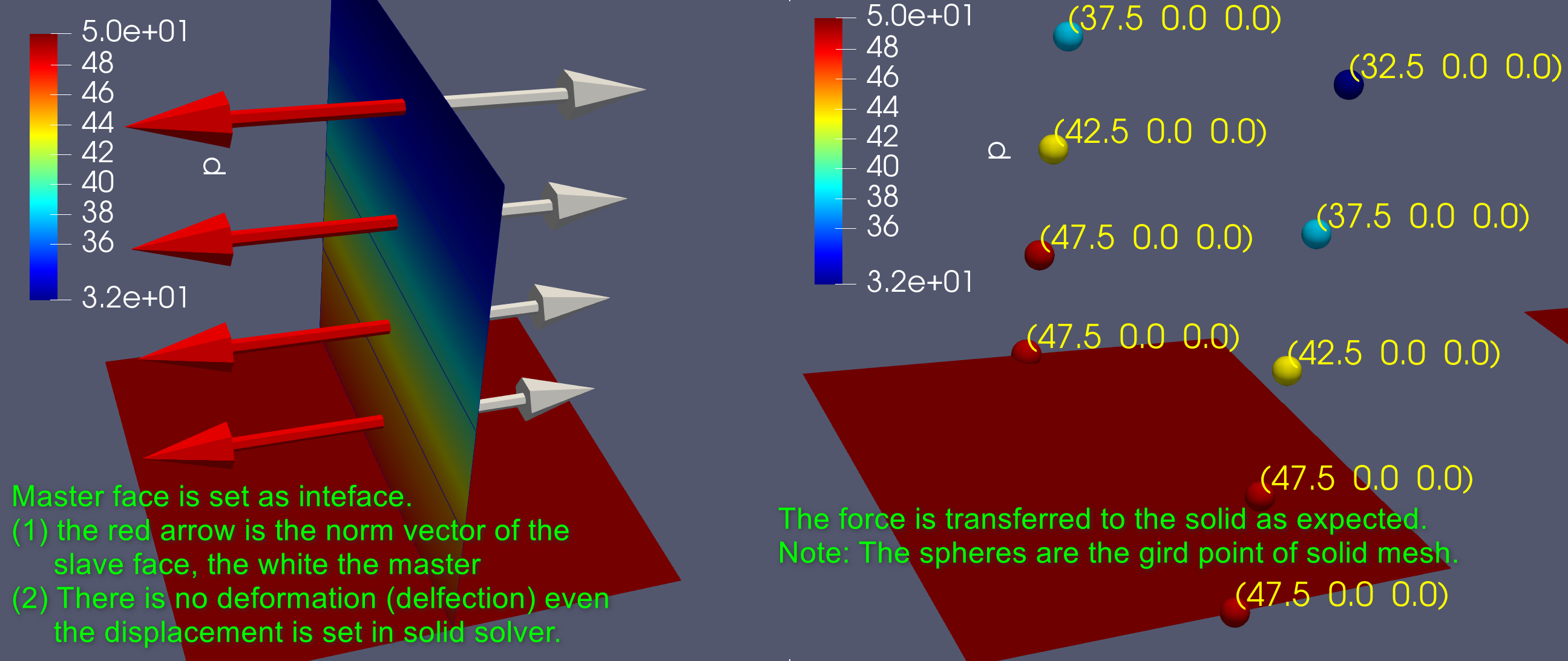
The Force directions are opposite they should be. For example, the front face points to the upstream, but the normal Force is also pointing to the upstream.
If someone is interested in this case, I can pack and upload the code here. My solid solver is very simple written in Python. Its purpose is just receiving data from Fluid to test the coupling is going well.
The second question seems resolved. The force directions of the interface in fluid and solid should be opposite, since one is force acted on the fluid, the other is acted on the solid. Since I observed the normal direction of the master face in Fluid and compared with the force in solid, my previous conclusion is wrong. I should compare both the face normal and force direction in Fluid or in Solid not one in Fluid the other in Solid. Am I understanding this right?